Reverse-Engineering the Front Panel of a WatchGuard T40
04 Oct 2025with linux mostly working on the T40, i decided to take a look at getting the front panel LEDs and buttons working.
Preparation
to prepare for this, we first need to dump the file system and figure out what controls the front panel. the ssd is easily dumpable from the - now - working linux system.
as for what controls the front panel, the boot log mentions a S51armled script, which probably does something with the front panel (just a hunch).
looking at that script, it just runs /usr/bin/armled -arm, so let’s look at that binary.
The armled Binary
i didn’t actually look much at this binary, as i suspected it would work similar to how the T70’s front panel works, meaning theres a library doing the actual work.
and i was right, the armled binary links agains libwgpanel.so.
that seems promising, so let’s look at that library.
libwgpanel.so
after loading and analyzing the library in ghidra, there’s a bunch of functions exported. that’s really nice.
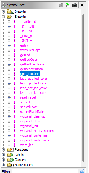 |
|---|
| exports of libwgpanel.so |
while write_led, getResetButton, and read_reset would be obvious candidates to look at, i decided to start with gpio_initialize.
for now, i care more about understanding how things work generally, not specifically how to do stuff.
the rest i can hopefully figure out from that.
so, let’s look at gpio_initialize.
gpio_initialize and friends
gpio_initialize calls two functions, which i don’t care too much what they do right now.
digging a bit in the first one tho, we see some familiar looking code (post clean-up here):
bool export_gpio_pin(char *gpio_pin)
{
  bool fn_rc;
  int rc;
  size_t len;
  stat *stat_buf;
  char gpio_path [84];
  undefined4 local_c;
  FILE *fhandle;

  sprintf(gpio_path,s_/sys/class/gpio/gpio%s/value_00114240,gpio_pin);
  rc = xstat(gpio_path,&stat_buf);
  if (rc == 0) {
    fn_rc = true;
  }
  else {
    fhandle = fopen(s_/sys/class/gpio/export_00114198,"wb");
    if (fhandle == (FILE *)0x0) {
      fn_rc = true;
    }
    else {
      len = strlen(gpio_pin);
      len = fwrite(gpio_pin,len,1,fhandle);
      local_c = (undefined4)len;
      fclose(fhandle);
      fn_rc = false;
    }
  }
  return fn_rc;
}
this function seems to handle exporting a gpio pin, using the standard sysfs gpio interface.
the parent function, the only one calling export_gpio_pin, seems to take a list of gpio pins (as a flat string of all things!) to export.
i suspect the parameter type is wrong tho, probably it should be an array of some struct. this is also true for export_gpio_pin.
bool export_gpio_pin_list(char *gpio_list_maybe)
{
  bool bVar1;
  char *gpio_name_i;

  gpio_name_i = gpio_list_maybe;
  while( true ) {
    if (*gpio_name_i == '\0') {
      return false;
    }
    if (((*gpio_name_i != '-') && (*(int *)(gpio_name_i + 0x14) == 0)) &&
       (bVar1 = export_gpio_pin(gpio_name_i), bVar1)) break;
    gpio_name_i = gpio_name_i + 0x20;
  }
  return true;
}
doing the same for the other function called by gpio_initialize, we see it also uses the sysfs gpio interface, this time to initialize the direction (and pull-ups?) of the pins.
from the code, we also get a lot of clues as to what the misterious structure actually is:
bool set_gpio_mode(s_gpio_pin_entry *gpio_pin)
{
  int strncmp_result;
  size_t len;
  char acStack_70 [8];
  char s_none [8];
  char file_path [84];
  undefined4 local_c;
  FILE *fhandle;

  builtin_strncpy(s_none,"none",5);
  if (gpio_pin->pin_name[0] == '-') {
    return false;
  }
  if (gpio_pin->unkn1 == 0) {
    sprintf(file_path,s_/sys/class/gpio/gpio%s/direction_001141d0,gpio_pin);
    fhandle = fopen(file_path,"wb");
    if (fhandle == (FILE *)0x0) {
      return true;
    }
    len = strlen(gpio_pin->direction);
    len = fwrite(gpio_pin->direction,len,1,fhandle);
    local_c = (undefined4)len;
    fclose(fhandle);
                    // gpio_pin->direction == "in"
    strncmp_result = strcmp(gpio_pin->direction,"in");
    if (strncmp_result == 0) {
      sprintf(file_path,s_/sys/class/gpio/gpio%s/active_lo_00114218,gpio_pin);
      fhandle = fopen(file_path,"wb");
      if (fhandle == (FILE *)0x0) {
        return true;
      }
      sprintf(acStack_70,"%d",(ulong)(uint)gpio_pin->active_lo);
      len = fwrite(acStack_70,1,1,fhandle);
      local_c = (undefined4)len;
      fclose(fhandle);
      sprintf(file_path,s_/sys/class/gpio/gpio%s/edge_001141f8,gpio_pin);
      fhandle = fopen(file_path,"wb");
      if (fhandle == (FILE *)0x0) {
        return true;
      }
      len = strlen(s_none);
      len = fwrite(s_none,len,1,fhandle);
      local_c = (undefined4)len;
      fclose(fhandle);
    }
                    // gpio_pin->direction == "out"
    strncmp_result = strcmp(gpio_pin->direction,"out");
    if (strncmp_result == 0) {
      write_led(gpio_pin,gpio_pin->initial_level);
    }
  }
  else if (gpio_pin->unkn1 == 1) {
    write_led(gpio_pin,gpio_pin->initial_level);
  }
  return false;
}
from the clues, i think the struct looks something like this:
struct s_gpio_pin_entry {
  char pin_name[16]; // as you'd write to /sys/class/gpio/export
  char direction[4]; // "in" or "out"
  int unkn1; // 1 or 0, idk what it does
  int active_lo; // 1 or 0, if the pin is active low. "in" direction only
}
the calling function also makes a lot of sense with that struct in mind:
bool set_gpio_mode_list(s_gpio_pin_entry *gpio_pins)
{
  bool fail;
  s_gpio_pin_entry *pin;

  pin = gpio_pins;
  while( true ) {
    if (pin->pin_name[0] == '\0') {
      return false;
    }
    fail = set_gpio_mode(pin);
    if (fail) break;
    pin = pin + 1;
  }
  return true;
}
those findings also check out with the previous export_gpio_pin and export_gpio_pin_list functions:
bool export_gpio_pin(s_gpio_pin_entry *gpio_pin)
{
  bool fn_rc;
  int rc;
  size_t len;
  stat *stat_buf;
  char gpio_path [84];
  undefined4 local_c;
  FILE *fhandle;

                    // exports a gpio pin using /sys/class/gpio/export
  sprintf(gpio_path,s_/sys/class/gpio/gpio%s/value_00114240,gpio_pin);
  rc = xstat(gpio_path,&stat_buf);
  if (rc == 0) {
    fn_rc = true;
  }
  else {
    fhandle = fopen(s_/sys/class/gpio/export_00114198,"wb");
    if (fhandle == (FILE *)0x0) {
      fn_rc = true;
    }
    else {
      len = strlen(gpio_pin->pin_name);
      len = fwrite(gpio_pin,len,1,fhandle);
      local_c = (undefined4)len;
      fclose(fhandle);
      fn_rc = false;
    }
  }
  return fn_rc;
}

bool export_gpio_pin_list(s_gpio_pin_entry *gpio_pins)
{
  bool fail;
  s_gpio_pin_entry *pin;

  pin = gpio_pins;
  while( true ) {
    if (pin->pin_name[0] == '\0') {
      return false;
    }
    if (((pin->pin_name[0] != '-') && (pin->unkn1 == 0)) && (fail = export_gpio_pin(pin), fail))
    break;
    pin = pin + 1;
  }
  return true;
}
with that, we arrive at a pretty good understanding of what gpio_initialize does:
bool gpio_initialize(s_gpio_pin_entry *gpio_list)
{
  bool fail;

  fail = false;
  if (gpio_initialize_ran == 0) {
    gpio_initialize_ran = 1;
    fail = export_gpio_pin_list(gpio_list);
    if (!fail) {
      fail = set_gpio_mode_list(gpio_list);
    }
  }
  return fail;
}
A THUNK to remember
all that we need now is to find who calls gpio_initialize, and what parameter it uses.
if we find that parameter, we have everything we need.
at first this seems bad, gpio_initialize only has one caller, and that’s all messed up:
void gpio_initialize(void)
{
  gpio_initialize();
  return;
}
that matches nothing of what we expect.
but fear not, this is just some weirdness with how ghidra decompiled the code. looking at the disassemly, there’s a big label calling this thing a “THUNK FUNCTION”. now, what is that?!
 |
|---|
| me when thunk function |
a quick search reveals that, simply put, a thunk function is just a intermediate function that does nothing but call another function. it’s a bit special tho, as it only branches to the target, without messing with the stack or registers. thus, ghidra doesn’t show any parameters or return value, as there technically aren’t any. instead, they are just passed through.
gpio_initialize was likely thunked because it’s an export symbol, but that’s just speculation on my part.
Discovering The Button GPIOs
anyway, going to the single caller of the thunked gpio_initialize, we luckily find something that makes more sense:
void FUN_00101d44(void)

{
  gpio_initialize(&DAT_00114128);
  read_reset(&DAT_00114128);
  return;
}
looks like we found our parameter!
cleaning it up (and adding the global as a dummy), we get:
void something_gpio_initialize_and_read_reset(void)
{
  gpio_initialize(&G_GPIO_LIST);
  read_reset(G_GPIO_LIST);
  return;
}

s_gpio_pin_entry G_GPIO_LIST[/*?*/] = {
  // ...
};
from the read_reset call, we can also guess that the first entry will be the reset button, and the rest will be leds.
now we just have to type the global, and we’re done.
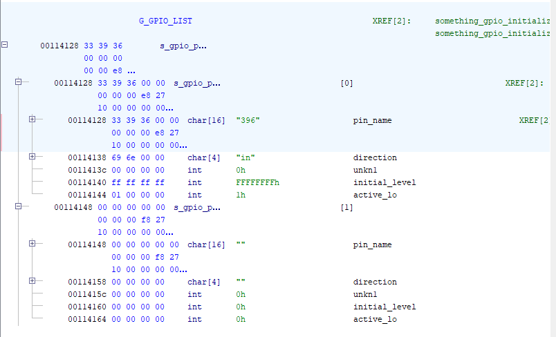 |
|---|
| wait, there’s only one? |
of course, it would’ve been to easy if it actually contains all entries. there must be another global where the leds are defined, and this is just the buttons.
but first, let’s note what we’ve found here:
| Pin # | Direction | Active Low? | Initial Level | Description |
|---|---|---|---|---|
| 396 | in | yes | - | Reset Button |
A Small Problem
So, GPIO pin 396 is the reset button, active low, input only. That makes sense, only one problem: the first GPIO number in linux is 512. writing to 396 will just error out.
something must have changed to the GPIO numbering scheme from Linux 4.6 (Stock OS) to 6.16 (what I’m using)…
another issue is that i cannot find any other globals that look like a list of s_gpio_pin_entry structs, or another call to gpio_initialize.
i think with a bit more time, i could figure this out, but for now i’ll try something else.
Poking Around
because the LS1043a only has 128 GPIO lines, i guessed that the gpio numbers in the older kernel would have some offset, and that my reset button was on the lower end. i also took a guess that the leds would be nearby, because why would you route the signals all over the place?
with that, i started poking around the GPIOs, randomly writing stuff to them, in the hopes that i don’t kill something important. and suddenly, one of the leds changed!
weirdly, when i toggled the same GPIO (539) again, a different led changed. what the heck?
Figuring Out the LEDs and their Shift Register
a look at the board revealed that near the front panel leds, there’s a LV164A shift register. and we’ve just found the clock pin!
let’s just guess and assume that the data pin is either one up or one down from the clock pin. trying both, we find that indeed, GPIO 540 is the data pin!
with that, we can now control the front panel leds, by bit-banging the shift register:
#!/bin/bash

SHIFT_CLOCK_PIN=539
DATA_OUT_PIN=540
PATTERN="$1"

if [ -z "$PATTERN" ]; then
  echo "Usage: $0 <bitpattern>"
  exit 1
fi

[ ! -d /sys/class/gpio/gpio$SHIFT_CLOCK_PIN ] && echo "$SHIFT_CLOCK_PIN" > /sys/class/gpio/export
[ ! -d /sys/class/gpio/gpio$DATA_OUT_PIN ]   && echo "$DATA_OUT_PIN"   > /sys/class/gpio/export

echo out > /sys/class/gpio/gpio$SHIFT_CLOCK_PIN/direction
echo out > /sys/class/gpio/gpio$DATA_OUT_PIN/direction

for ((i=0; i<${#PATTERN}; i++)); do
  bit=${PATTERN:i:1}
  if [ "$bit" != "0" ] && [ "$bit" != "1" ]; then
    echo "Invalid bit '$bit' in pattern"
    exit 2
  fi

  echo "$bit" > /sys/class/gpio/gpio$DATA_OUT_PIN/value

  echo 0 > /sys/class/gpio/gpio$SHIFT_CLOCK_PIN/value
  echo 1 > /sys/class/gpio/gpio$SHIFT_CLOCK_PIN/value
done
here’s the patterns for the different leds. note however that the pattern is shifted MSB first, so the first value in the pattern ends up on the last led. secondly, the leds are active low, so a 0 lights up the led.
| Pattern | LED |
|---|---|
| x000 | Mode |
| 0x00 | Status |
| 00x0 | Attention |
| 000x | Failover |
why the hardware is setup with a shift register, when there’s plenty of GPIOs available, is beyond me. must’ve been cheaper than a bunch of transistors…
Finding the Reset Button
for the reset button, i simply dumped the current GPIO state for all GPIOs not set to output, once with and once without pressing the button. i then passed the outputs into diff, and voila, GPIO 620 is the reset button!
#!/bin/bash
for pin in {512..640}; do
  [ ! -d /sys/class/gpio/gpio$pin ] && echo "$pin" > /sys/class/gpio/export

  dir=$(cat /sys/class/gpio/gpio$pin/direction)
  if [ "$dir" != "in" ]; then
    continue
  fi

  val=$(cat /sys/class/gpio/gpio$pin/value)
  echo "#$pin = $val"
done
TL;DR Pin Mapping
the pin mapping is:
| Pin # | Direction | Description |
|---|---|---|
| 539 | out | LED Shift Register Clock |
| 540 | out | LED Shift Register Data |
| 620 | in | Reset Button, low when pressed |
the leds are controlled by a LV164A shift register, the first four outputs connect to the front panel leds. outputs of the leds are inverted, so a low level lights up the led.
| LV164A Pin | LED |
|---|---|
| $Q_A$ | Failover |
| $Q_B$ | Attention |
| $Q_C$ | Status |
| $Q_D$ | Mode |
Controlling the Front Panel from U-Boot
after doing all that, i noticed that the U-Boot of the T40 has a convenient 74lv164 command for controlling the shift register, and with that, the front panel leds.
would’ve been nice to know that earlier, but oh well.
command usage is simple:
=> 74lv164 low  #-> all leds on
=> 74lv164 high #-> all leds off
=> 74lv164 qa 0 #-> failover
=> 74lv164 qb 0 #-> attn
=> 74lv164 qc 0 #-> status
=> 74lv164 qd 0 #-> mode
Conclusion
while i would’ve liked to fully reverse-engineer the libwgpanel.so library, but even if i found the pin mapping there, they wouldn’t map to the current kernel’s GPIO numbering anyway.
while my final solution isn’t very elegant, it works, and so i think i’ll leave it at that.