Reverse-Engineering the Front Panel of a WatchGuard T70
18 Sep 2025in the previous posts, we explored how to jailbreak a watchguard t70 and run linux on it. sadly, by default the front panel (leds, reset button) are not functional in linux. let’s change that by reverse-engineering the custom kernel module that watchguard uses in their own os.
Finding the Module
Note:
for whatever reason, i decided to do this on a T55 first. since it’s basically the same hardware, everything applies to the T70 as well.
just by taking a quick look at the bootlog of the stock os we find a very interesting line:
LED/Reset Button Driver for MB-UP2010W...
that sounds like exactly what we are looking for!
searching a bit around the line, we can see that the module seems to be loaded by a init script /etc/runlevel/1/S09sled_drv, as well as some debug output from the module itself:
[   17.023341] Running /etc/runlevel/1/S09sled_drv...
[   16.645496] sled_drv_t55: loading out-of-tree module taints kernel.
[   16.652895] <chv_pinctrl_probe> Invoked!
[   16.657302] <chv_pinctrl_probe>: probe res check, IORESOURCE_MEM: start=00000000fed80000, end=00000000fed87fff, name=INT33FF:00
[   16.670182] <chv_pinctrl_probe>: probe res check pctrl->regs = ffffc90000430000
[   16.678364] <chv_pinctrl_probe>: probe res check, IORESOURCE_MEM: start=00000000fed88000, end=00000000fed8ffff, name=INT33FF:01
[   16.691219] <chv_pinctrl_probe>: probe res check pctrl->regs = ffffc90000440000
[   16.699397] LED/Reset Button Driver for MB-UP2010W...
looking at the init script, it’s fairly simple and just loads a kernel module /lib/drivers/sled_drv-t55.ko or /lib/drivers/sled_drv-t70.ko depending on the model.
the following is pseudo-code of the script, as i’m not quite sure about the copyright status.
dir="/lib/drivers"

model=wg.get_model()

if (model == "T70") then
  wg.insmod(dir .. "sled_drv-t70.ko")
elseif (model == "T55" or model == "T55-W") then
  wg.insmod(dir .. "sled_drv-t55.ko")
end
so, the module we are looking for is /lib/drivers/sled_drv-t70.ko and /lib/drivers/sled_drv-t55.ko (both are present on both models, as they use the same firmware image).
now, let’s extract the module and load it into ghidra.
Understanding the Module
looking at the (what i assume to be) entry point of the module, we can see that it maps some (I/O) memory regions, then calls a function sled_init.
this already is very useful information, as on intel braswell (the cpu), gpio is handled through memory-mapped i/o.
even better, referencing iomap.h of the coreboot project, we can see that the start addresses of the mapped regions correspond to the gpio controllers, specifically the GPIO Communities SouthWest (at 0xfed80000) and North (at 0xfed88000).
ulong likely_entry_point(long param_1)
{
  // (...)
  printk("<%s> Invoked!\n","chv_pinctrl_probe");
  // (...)

                  // for each resource
  do {
    printk("<%s>: probe res check, IORESOURCE_MEM: start=%p, end=%p, name=%s\n",
    "chv_pinctrl_probe",*current_res,current_res[1],current_res[2]);
                  // -> <chv_pinctrl_probe>: probe res check, IORESOURCE_MEM:
                  // start=00000000fed80000, end=00000000fed87fff, name=INT33FF:00
                  // -> <chv_pinctrl_probe>: probe res check, IORESOURCE_MEM:
                  // start=00000000fed88000, end=00000000fed8ffff, name=INT33FF:01
    rc = devm_ioremap_resource(dev,current_res);
    *res_ptr = rc;

    printk("<%s>: probe res check pctrl->regs = %p\n","chv_pinctrl_probe",rc);
                  // -> <chv_pinctrl_probe>: probe res check pctrl->regs = ffffc90000430000
                  // -> <chv_pinctrl_probe>: probe res check pctrl->regs = ffffc90000440000

    current_res = current_res + 8;
  } while ((ledmappings_entry *)current_res != ledmappings);

  // (...)
  sled_init((undefined *)likely_pctrl);
}
next, looking at sled_init, we see a character device is registered.
that must be how the front panel is controlled from userspace.
(side-note: there’s actually a whole library, t55-libwgpanel.so, that abstracts the ioctl calls to the character device, but we won’t look at that here.)
int sled_init(undefined *likely_pctrl)
{
  int err;

  printk("\x015LED/Reset Button Driver for MB-UP2010W...\n");
  err = __register_chrdev(0xf0,0,0x100,"sled_drv",&chrdev_fops);
  // (...)
}
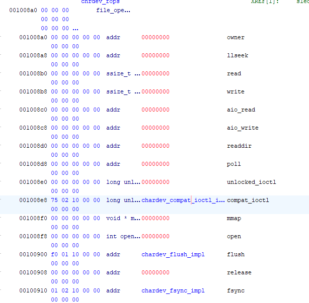
(partially) defining the file_operations struct and correctly typing the chrdev_fops global, we see that compat_ioctl, flush and fsync are implemented.
the latter two aren’t really interesting, but compat_ioctl is where the actual functionality is implemented.
basically, it boils down to calling one of two functions (set_led_off and set_led_on), depending on the command and argument passed to the ioctl.
 |
|---|
chrdev_fops global |
we’re almost there!
set_led_on and set_led_off are quite simple, they just call a lookup function findled to (presumably) convert an led id to a gpio pin, then call a write function to actually write to the pin.
void set_led_on(undefined *pinctl,int led_no)
{
  ledmappings_entry *led = findled(led_no);
  if (led != nullptr) {
    likely_write_led_gpio(pinctl,led->gp_pad,led->led_on_level);
  }
}
finally, let’s look at how findled figures out the mapping.
it’s actually quite simple, it just iterates over a static array of mappings (ledmappings) and returns the one that matches the given id.
the original code may have looked something like this:
// ... foreshadowing ...
#define WG_LED_STATUS 0
#define WG_LED_ATTN 2
#define WG_LED_MODE 3
#define WG_LED_FAILOVER 4

struct ledmappings_entry {
  int led_no;
  int gp_pad;
  int led_on_level;
};

struct ledmappings_entry ledmappings[] = {
  { WG_LED_STATUS, 7, 0 },
  { WG_LED_ATTN, 3, 0 },
  { WG_LED_MODE, 1, 0 },
  { WG_LED_FAILOVER, 5, 0 },
}

ledmappings_entry* findled(int led_no)
{
  for (int i = 0; i < COUNT_OF(ledmappings); i++) {
    if (ledmappings[i].led_no == led_no) {
      return &ledmappings[i];
    }
  }

  return nullptr;
}
and now, we (almost) have the pins mapped out! only one problem remains: the driver maps two gpio controllers, but we don’t know which pin belongs to which controller.
while i could probably spend a lot of time figuring that out too, i opted to simply try out both options and see what happens. what’s the worst that could happen, right?
 |
|---|
| let’s gambling |
Note on Reverse-Engineering Steps
the steps shown above are very high-level and skip a lot of details, and are also in a different order than i actually did them.
for example, the chain leading to ledmappings was basically in reverse, as ledmappings, findled, set_led_on and set_led_off were actually exported symbols (thus i knew their names).
also, there were some “side-quests”, like taking a quick look at ``t55-libwgpanel.so` and other binaries, to understand how the leds are controlled from userspace.
still, i think the above rendering makes it easier to understand the overall flow, even if it doesn’t quite match the actual steps taken.
Finalizing the Pin Mapping for Linux
looking at the gpio implementation in linux, we see that gpio communities SouthWest and North are mapped to gpiochip0 (GPIOs 512-609) and gpiochip1 (610-682) respectively.
# cat /sys/kernel/debug/gpio
gpiochip0: GPIOs 512-609, parent: platform/INT33FF:00, INT33FF:00:
gpiochip1: GPIOs 610-682, parent: platform/INT33FF:01, INT33FF:01:
gpiochip2: GPIOs 683-709, parent: platform/INT33FF:02, INT33FF:02:
(...)
using the gp_pad values from the ledmappings array as an offset to the first pin of each chip, we get some potential linux GPIOs.
poking those pins and observing, we can finally figure out which pin does what.
led_no |
gp_pad |
# when on GP_SouthWest (@ 512) | Reaction when Poked | # when on GP_North (@ 610) | Reaction when Poked |
|---|---|---|---|---|---|
| 3 | 1 | 513 | None | 611 | Mode LED |
| 2 | 3 | 515 | None | 613 | ATTN LED |
| 4 | 5 | 517 | None | 615 | Fail Over LED |
| 0 | 7 | 519 | None | 617 | Status LED |
and there we have it, we can now control the front panel leds from linux! to be honest, i don’t really understand why they mapped GP_SouthWest at all, but seeing how the T70 driver only maps GP_North, maybe it was just an oversight.
What about the Reset Button?
while sled_drv probably also somehow implements the reset button, i decided to just keep gambling and poke nearby pins on GP_North.
that should be a safe bet, as it’s generally convenient to place similar components close to each other when creating a schematic (at least that’s what i would do).
turns out, the first pin i tried (610) was indeed the reset button! testing the other pins (612, 614, 616), the first two seem to handle some internal functions (indicated by status leds on the board), while 616 does nothing.
How to try it out
if you want to try it yourself, you can use the following commands (as root; tested on ubuntu server 24.04):
gpio=611  # Mode LED

echo "$gpio" > /sys/class/gpio/export
echo "out" > /sys/class/gpio/gpio$gpio/direction

echo "1" > /sys/class/gpio/gpio$gpio/value
# or
echo "0" > /sys/class/gpio/gpio$gpio/value
and for the reset button:
gpio=610  # Reset Button

echo "$gpio" > /sys/class/gpio/export
echo "in" > /sys/class/gpio/gpio$gpio/direction

level=$(cat /sys/class/gpio/gpio$gpio/value)
echo "$level"
a full mapping of the pin functions is as follows:
| Supported Model | GPIO Pin | Function | Notes |
|---|---|---|---|
| T55 & T70 | 610 | Reset Button | 0=Pressed, 1=Released |
| T55 & T70 | 611 | Mode LED | 0=ON, 1=OFF |
| T70 | 612 | LED near backplane NIC | 0=OFF, 1=ON |
| T55 & T70 | 613 | ATTN LED | 0=ON, 1=OFF |
| T55 | 614 | LED near switch IC | 0=OFF, 1=ON |
| T70 | 614 | LED near network ports / power switch | 0=OFF, 1=ON |
| T55 & T70 | 615 | Fail Over LED | 0=ON, 1=OFF |
| T55 & T70 | 617 | Status LED | 0=ON, 1=OFF |